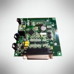
Product purpose
The MK10.7s controller is intended for use as an embedded, high-performance system for direct digital control of various types of motors, frequency converters and secondary stabilized and autonomous power supply systems. Products with controllers can be combined into a distributed system of automatic control of technological equipment by a local industrial network based on a galvanically isolated CAN interface. The controller provides a functional replacement for the MK10.6 controller.
Distinctive features:
- better price/performance ratio;
- it is the next generation of simple embedded controllers, being an improved analogue of the MK10.6 controller;
- increased number of PWM outputs;
- universal connector with digital inputs/outputs;
- increased volume of non-volatile memory for parameters;
- the ability to connect additional expansion boards.
Key specifications
| Parameter name | Value |
|---|---|
| Microcontroller type | TMS320F28035 |
| Clock frequency, MHz | 60 |
| One operation processing time, ns | 16,67 |
| Built-in program memory | 64 Kword |
| Built-in data memory | 10 Kword |
| Protection of firmware with security codes | Yes |
| External hardware | |
| External non-volatile parameter memory with I2C interface | 16 Kword, type 24LC256 |
| External real time clock with I2C interface | Yes, type DS1340C |
| Power inverter interface | |
| PWM outputs type | open collector |
| Number of main PWM outputs | 6 |
| Number of additional PWM outputs | 5 |
| Hardware fault inputs | 4 |
| Analog inputs | |
| Number of channels in format ±3.3V, pcs. | 4 |
| Number of channels in format 0 – 6.6 V, pcs. | 6 |
| ADC bit depth, bit | 12 |
| Conversion time per one channel, ns | 500 |
| Integrated indication | |
| Indication of input power, LED color | “Green” |
| Indication of digital circuits power, LED color | “Green” |
| Indication of “Fault” condition | “Red” |
| Indication of “Run/Stop” mode | “Yellow” |
| CAN interface | |
| Galvanic isolation, voltage, V | yes, 500V |
| Maximum voltage on CAN bus, V | ±80 |
| Maximum baudrate, Mbaud/s | 1 |
| SPI interface | |
| Maximum bitrate, Mbit/s | 5 |
| Number of adressed devices, pcs. | 1 |
| Output format | TTL |
| Discrete outputs with galvanic isolation | 2 |
| Discrete inputs in “dry contact” format / Incremental encoder signal inputs in TTL format | 3 |
| Discrete outputs in “open collector” format | 3 |
| Discrete input in TTL format | 1 |
| Power supply | |
| Digital circuits power supply, V | 5±0.5 |
| Digital circuits maximum current consumption, A | 0,3 |
| Analog input conversion circuits power supply, V | ±15 |
| Analog input conversion circuits maximum current consumption, A | 0,03 |
| Power supply circuits protection | polarity reversal, power failure, short circuit |
| Price | Price and delivery time depends on the volume and stock. |
Documentation
User manual PDF


 Русский